
1-805-484-2992
Quotes - Engineering - SalesU-Tube Heat Exchangers For
Baffles and Tube Supports
U-Tube Duty
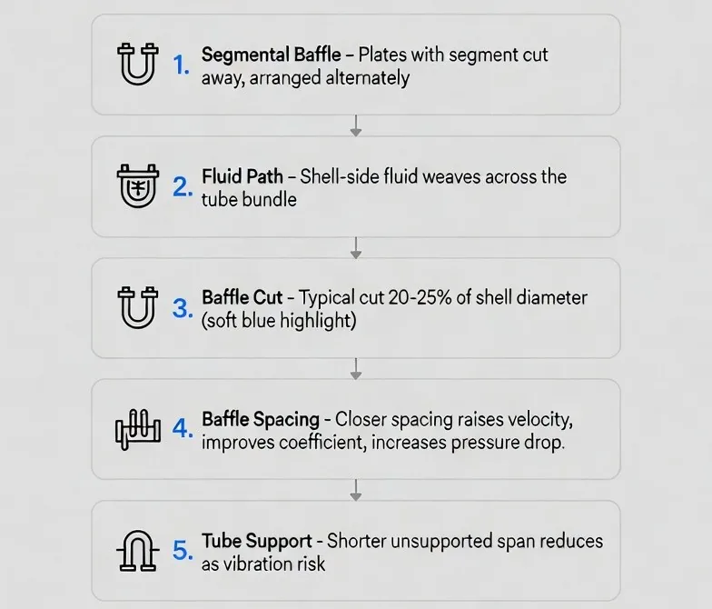
Baffles do two jobs that pull against each other. They direct shell-side flow across the tubes for heat transfer, and they support the tubes against vibration. Spacing them is a compromise between those two duties.
Segmental baffles are plates with a segment cut away, arranged alternately so the shell-side fluid weaves across the bundle. Cut is expressed as a percentage of shell diameter; around 20 to 25 percent is a normal starting point.
Spacing sets everything. Closer baffles mean higher cross-flow velocity, a better coefficient and higher pressure drop. They also shorten the unsupported tube span, which is the governing variable for vibration.
Bypass Is the Silent Performance Loss. Shell-side fluid takes the easiest path, and the clearances between bundle and shell, and between tube and baffle hole, are easy paths. Fluid that bypasses the bundle does no useful work.
Sealing strips placed in the bypass lanes push flow back through the tube field. On large bundles this is worth real percentage points of performance and is far cheaper than the extra surface area needed to compensate for its absence.
Tie rods and spacers. These hold the baffle assembly at the correct pitch and give the bundle its rigidity. On a U-bundle they also carry the assembly during withdrawal, which is not a trivial load on a large unit.
Request a Quote



What the Baffle Layout Decides
Baffles direct shell-side flow across the tubes for heat transfer and support the tubes against vibration, and spacing them is a compromise between those two duties. Closer baffles mean higher cross-flow velocity, a better coefficient, higher pressure drop and a shorter unsupported span. Fluid that bypasses the bundle through the clearances does no useful work.
Segmental Baffles
Spacing & Vibration
Bypass & Support
Related
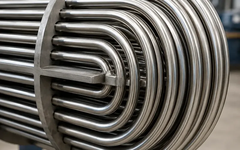
TUBE BUNDLE DESIGN • DESIGN
U-Bend Radius & Bending
Minimum radius, wall thinning and stress relief.
+ Learn More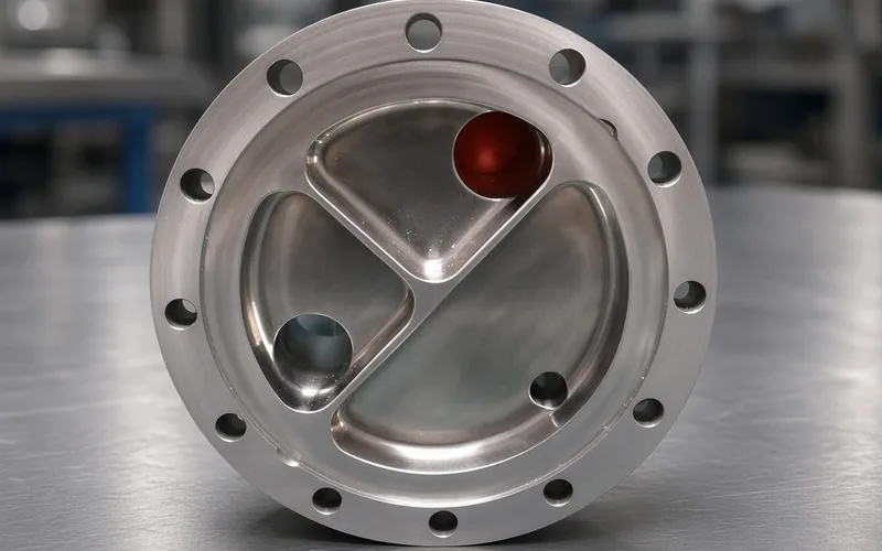
TUBE BUNDLE DESIGN • DESIGN
Tube Passes & Flow
The even-pass constraint and velocity targets.
+ Learn More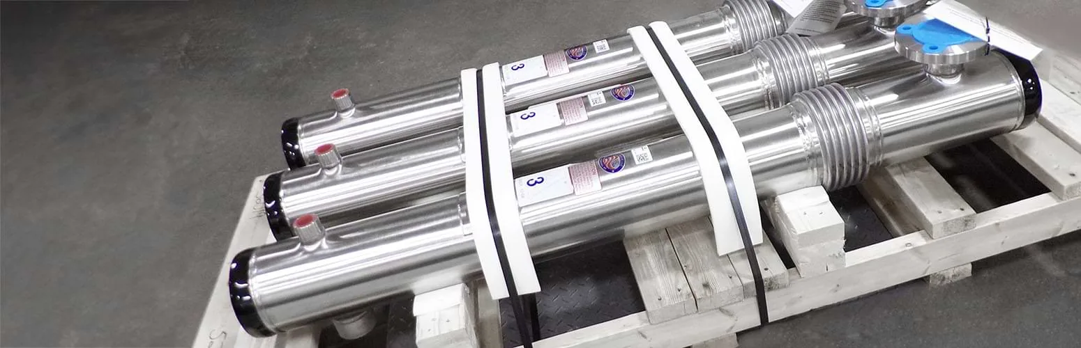
DESIGN • CONSTRUCTION
Tube Bundle Design
Bend radius, layout, passes, baffles and span.
+ Learn More