
1-805-484-2992
Quotes - Engineering - SalesU-Tube vs Straight Tube Exchangers
What You Gain and What You Lose
The cost argument for a U-tube is simple: one tubesheet instead of two, one head instead of two. The arguments against it are equally simple and worth stating plainly.
A straight tube bundle has a tubesheet at each end. A U-tube bundle has one, because the tubes turn around inside the shell and come back. That halves the tubesheets, removes the rear head entirely, and removes the rear pressure-boundary joint.
The cleaning limitation. A brush, rod or lance will not negotiate a 180 degree bend. Tube interiors can be cleaned chemically and the straight sections reached with high-pressure water, but full mechanical cleaning end to end is not available. This is the single most important consequence of the geometry.

Typical Construction
- Tubesheets: One, versus two on straight tube construction
- Rear head: None
- Rear pressure joint: None
- Thermal expansion: Free; no expansion joint needed
- Tube-side mechanical cleaning: Not available through the bend
- Tube passes: Even only, minimum two
- Tube replacement: Plugging in the field; bundle replacement otherwise
- Tube count: Slightly lower for the same shell, due to the untubed center lane
- Shell-side cleaning: Mechanical with the bundle withdrawn
- Best fit: Clean tube-side fluid, fouling or expanding shell side
A bundle with one tubesheet, in which each tube turns around inside the shell and returns. It removes the rear head and the rear pressure-boundary joint and lets the tubes grow freely, but the bends cannot be rodded.
U-Tube vs Straight Tube Exchangers
The pass limitation. Fluid enters one leg and leaves the other, so the pass count is always even. Where a duty needs a genuine temperature cross, an even-pass tube side cannot deliver true counterflow, and the answer is an F-shell, shells in series, or straight-tube construction.
Where the U-tube wins anyway. Free thermal expansion, no expansion joint, no rear seal, lower cost than a floating head, and full shell-side mechanical access. For duty with a clean tube side, that combination is hard to beat.
Put the Clean Fluid in the Tubes
This is the practical rule that follows from everything above, and it is the reverse of the usual advice for straight-tube exchangers where the fouling fluid normally goes tube-side because it is easier to clean there.
On a U-tube unit the cleanable side is the shell side. Treated cooling water, clean steam, refrigerant and closed-loop glycol belong in the tubes. Process streams that foul belong in the shell where the bundle can be pulled and the surface reached.
The Bend and What Follows
Because each tube is fixed at only one tubesheet, so it grows or shrinks freely into the shell and nothing restrains it. A straight tube bundle in a fixed tubesheet shell has both ends anchored, and the difference between tube growth and shell growth ends up as stress in the joints or a bellows. With a U-tube the only expansion question is whether the bends still clear the shell cover at full temperture, which the design handles with a length allowance. Cycling duty, steam service and liquid-to-liquid duty with a large temperature difference all benefit directly.
The lane runs the length of the bundle at the bend radius of the innermost row, and shell-side fluid will short-circuit through it if nothing blocks the gap. In a well-designed bundle the baffle plate spans that lane so flow is forced over the tubes, and sealing strips close the leakage path. When this is missed, the exchanger rates fine on paper and runs short on duty because a fraction of the shell flow never touches surface. It is one of the things to ask about on any bundle quoted as a drop-in replacement.
Usually not: a fixed tubesheet bundle cannot come out as a unit, so that exchanger is retubed in place one tube at a time, and a floating head bundle carries two tubesheets and a floating cover. A U-tube bundle is a single tubesheet, the tubes, the baffles and tie rods, so a drop-in replacement is the cheapest bundle to build. HeatX supplies new U-tube bundles to fit existing shells from the shell inside diameter, tubesheet outside diameter and thickness, tube count and layout, and the baffle spacing. That is a fraction of a new exchanger's cost.
Four passes make sense when the tube-side flow is low for the shell diameter and two passes would leave the velocity too slow to carry heat or keep the tubes clean. Doubling the passes doubles velocity and doubles the path length, so tube-side pressure drop rises roughly eightfold, so the pump must have the head available. On steam-to-water duty two passes are the norm. On liquid-to-liquid duty with a small cold-side flow, four passes often raise the coefficient enough to save a shell size. State the available pressure drop on each side when you Request a Quote.
Related
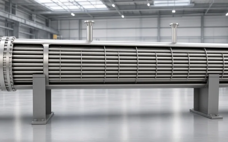
CONFIGURATION • TEMA
U-Tube vs Fixed Tubesheet
Cleaning access, expansion joints and thermal cycling.
+ Learn More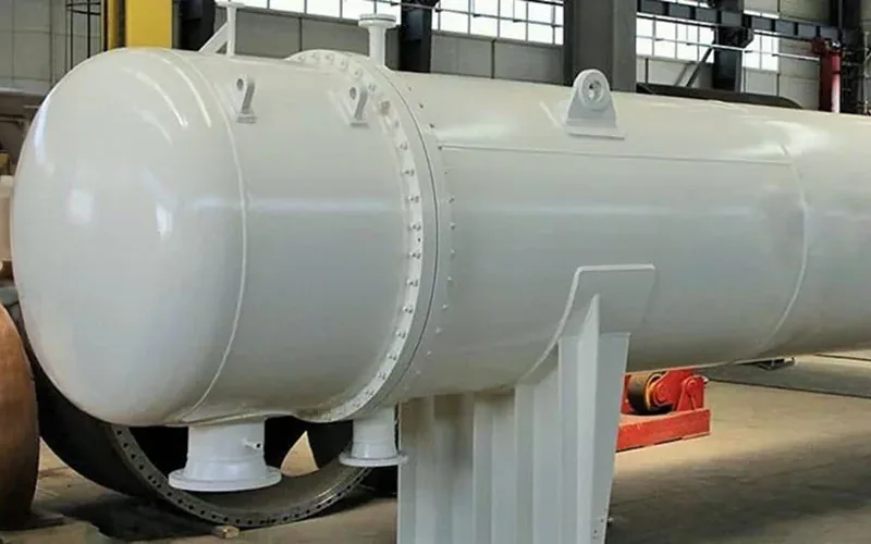
CONFIGURATION • TEMA
U-Tube vs Floating Head
Both pull and both expand; tube-side cleaning decides.
+ Learn More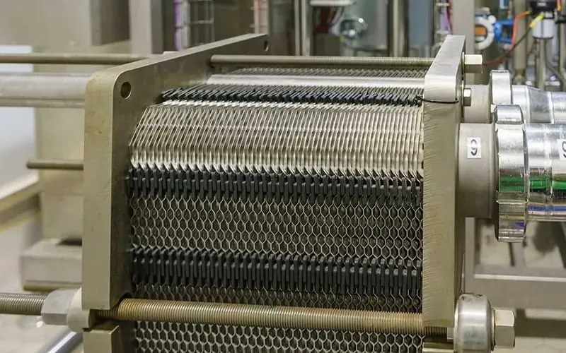
CONFIGURATION • TEMA
U-Tube vs Plate & Frame
Approach temperature and footprint against pressure limits.
+ Learn More